1) What is zonedata?Robot turning radius refers to the smooth transition of a robot when running two motion commands. If a turning radius is set, the robot will smoothly transition. The meaning of the turning radius is that when the robot enters a position within the set point radius, the robot begins to transition2) What is fine?If you want to accurately reach a location, use fine3) What is the difference between z0 and fine?On the trajectory, z0 is similar to fine. But besides accurate arrival, Fine also has a function to prevent program pre reading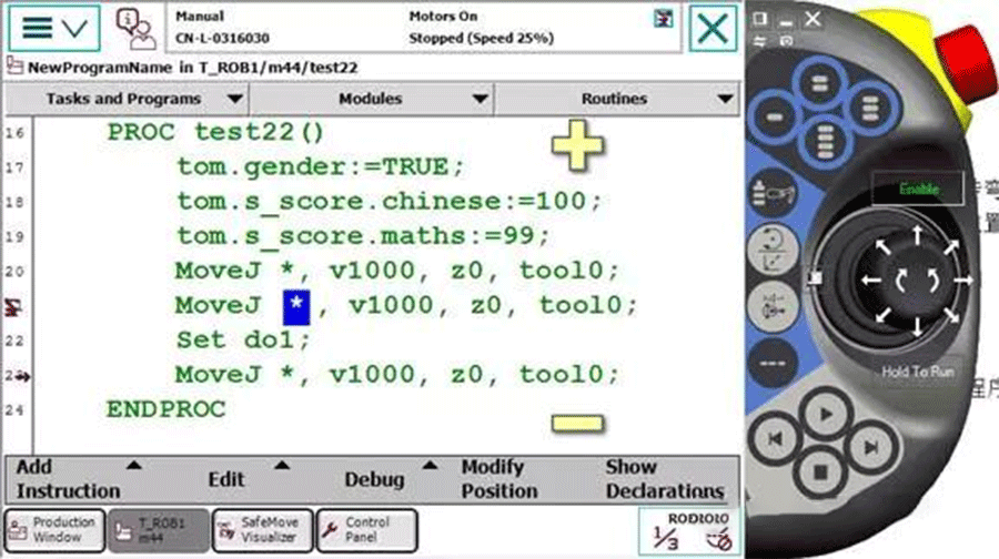
Using z0 in line 21 of Figure 1
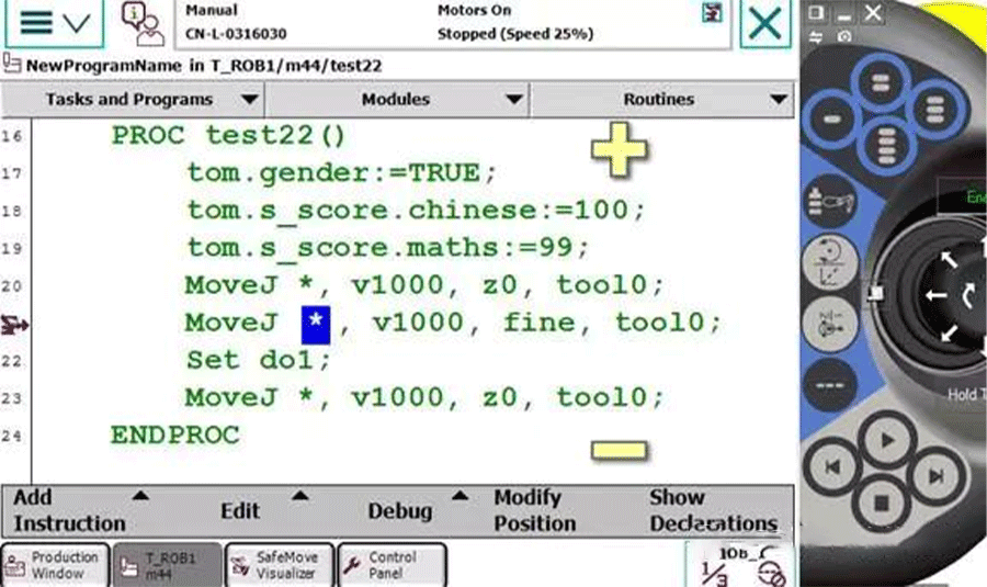
Figure 2, line 21, using fine
When the robot is running, the teaching pendant has two icons: one is the arrow on the left, indicating which line the program has read, and the other is the robot icon, indicating which line the robot is actually walking on. In order to achieve smooth transitions and other functions, the robot needs to read a few lines of code beforehand.If z0 in Figure 1 is used, the robot is walking on line 21 and the program has already been executed on line 23, which means the robot has not yet reached the position and has already opened doIf fine is used as shown in Figure 2, the robot is on line 21 while the program is still on line 21, indicating the presence of fine. The program pointer will not read in advance, meaning that the robot will only execute the open do after completing line 21.ABB Robot Programming Skills 11:Peter, CEO of Real time Robotics Technology: 1) If there are 6 product positions to be absorbed as shown in the above figure, how can we quickly create points? (Pure demonstration? Naive, it's too physically demanding.)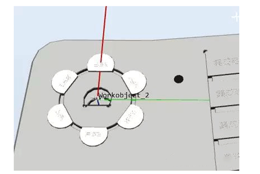 2) As shown in the figure below, we can observe that position 1 and position 0 have the same posture. Position 1 is offset by a radius relative to position 0, and positions 2-6 are also offset by a radius relative to position 0. Positions 2-6 are oriented towards the center of the circle. Since there are 6 points in the figure, starting from point 2, each point's pose has rotated 60 ° relative to point 1
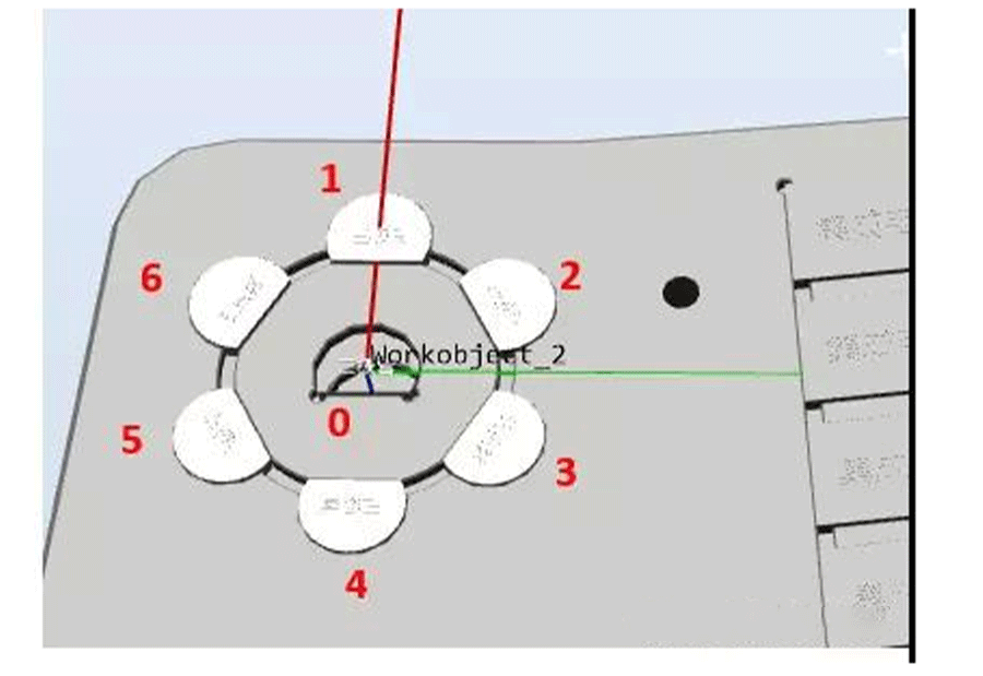 3) Is it possible to automatically calculate the positions of the other six points without teaching as long as the position of point 0 is taught and the radius is known (if unknown, measure it yourself)? The answer is definitely possible!!!4) Due to the involvement of coordinate system offset and rotation, it is necessary to ensure the accuracy of the tool and workpiece coordinate system5) Create a tool gridper_ dual, assuming that the z-direction is 100 and the tool's Z-direction is the extension direction of the tool
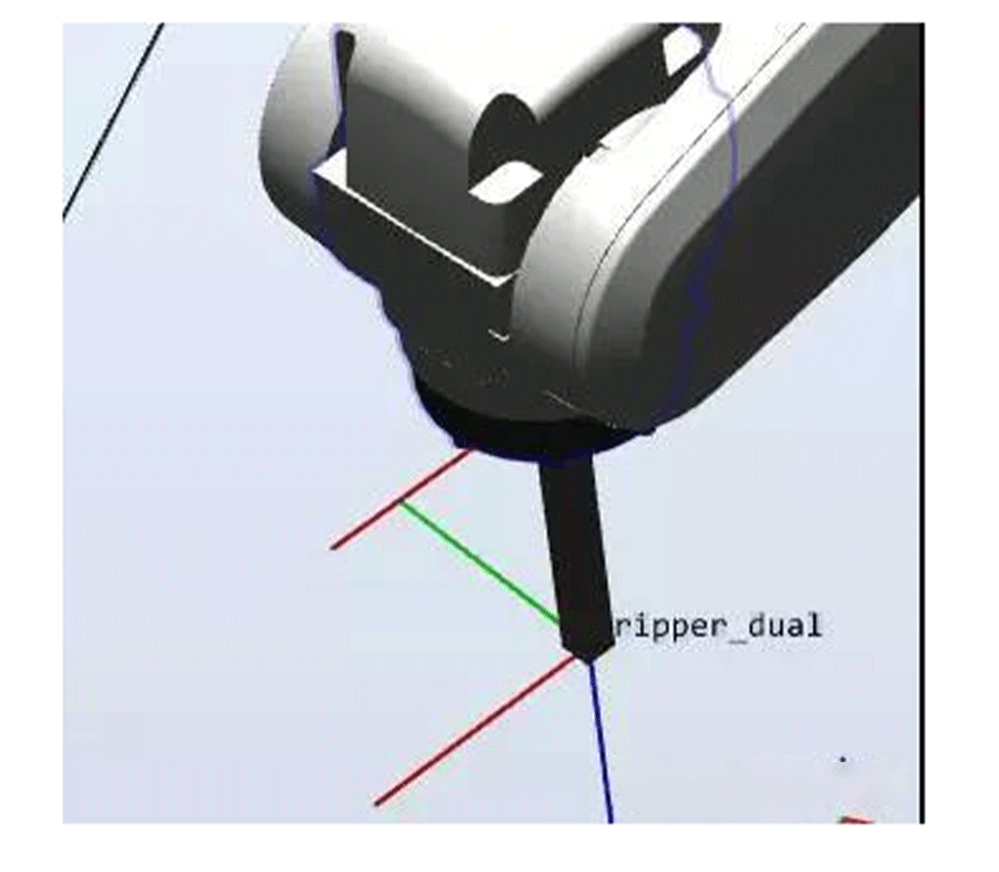 6) Create a coordinate system as shown in the following figure, with the center of the circle in the middle and the direction from 0 to 1 as X, as shown in the figure. The workpiece coordinate system in the following figure is facing downwards (following the right-hand rule). This is mainly created for the convenience of calculation.
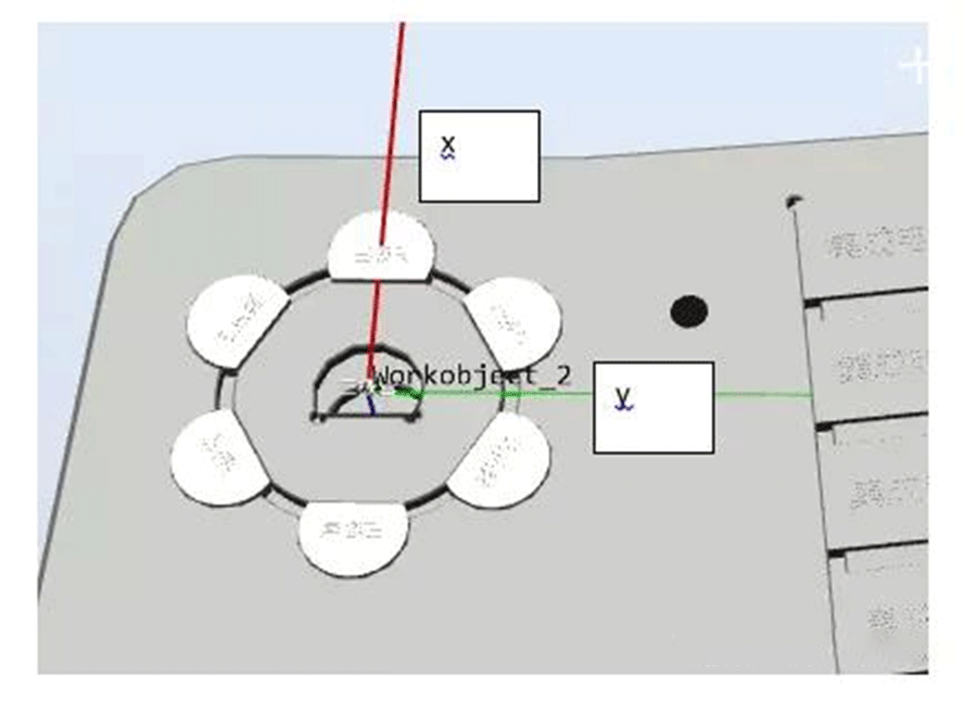 7) In the workwoobject2 coordinate system, under the gripper dual tool, teach the middle product position Target center. At this time, the Z of the tool must be perpendicular to the product plane, that is, the Z of the tool must face downwards. (Actually, we just need to use the pose and z of this point. The xy of this point is 0 because it is at the origin in the workobject2 coordinate system, where xy is 0.)8) Set the distance from the center of the circle to the first product (i.e. radius), for example 21.45mm9) We assume that the first position is called Target 1, then in the WorkObject 2 coordinate systemTarget1:=Target_center;! First, make sure that the position and posture of Target 1 are equal to that of Target CenterTarget1.trans.x:=radius*cos(60*0);! Recalculate the position of xTarget1.trans.y:=radius*sin(60*0);! Recalculate the position of yTarget1:=RelTool(Target1,0,0,0Rz:=0*60);! After obtaining the calculated positions x and y, TCP rotates around the tool's Z by 60 °.10) Based on the above example, the position of Target 1 is obtained, note that it is in the WorkObject 2 coordinate system.11) Combined with testing and other processes, it is relatively easy to complete the calculation and movement of 6 positions, as followsPROC main()radius:=21.45;count1:=1;WHILEcount1<7 DOrHome;cal;routine1;count1:=count1+1;ENDWHILEENDPROC PROC routine1()MoveJoffs(Target_temp,0,0,-30),v500,z1,gripper_dualWObj:=Workobject_2;MoveLTarget_temp,v500,z1,gripper_dualWObj:=Workobject_2;WaitTime 1;MoveLoffs(Target_temp,0,0,-30),v500,z1,gripper_dualWObj:=Workobject_2;ENDPROC PROC cal()Target_temp:=Target_center;TEST count1 CASE 1:Target_temp.trans.x:=radius*cos(60*(count1-1));Target_temp.trans.y:=radius*sin(60*(count1-1));Target_temp:=RelTool(Target_temp,0,0,0Rz:=(count1-1)*60);CASE 2:Target_temp.trans.x:=radius*cos(60*(count1-1));Target_temp.trans.y:=radius*sin(60*(count1-1));Target_temp:=RelTool(Target_temp,0,0,0Rz:=60); CASE 3:Target_temp.trans.x:=radius*cos(60*(count1-1));Target_temp.trans.y:=radius*sin(60*(count1-1));Target_temp:=RelTool(Target_temp,0,0,0Rz:=120);CASE 4:Target_temp.trans.x:=radius*cos(60*(count1-1));Target_temp.trans.y:=radius*sin(60*(count1-1));Target_temp:=RelTool(Target_temp,0,0,0Rz:=180);CASE 5:Target_temp.trans.x:=radius*cos(60*(count1-1));Target_temp.trans.y:=radius*sin(60*(count1-1));Target_temp:=RelTool(Target_temp,0,0,0Rz:=-120);CASE 6:Target_temp.trans.x:=radius*cos(60*(count1-1));Target_temp.trans.y:=radius*sin(60*(count1-1));Target_temp:=RelTool(Target_temp,0,0,0Rz:=-60);ENDTESTENDPROCPROC rHome()MoveJpHome,v500,z1,gripper_dualWObj:=wobj0;ENDPROCHoward


